Purpose of the flight and payload description
The objective of the flight was to measure the spectra of cosmic-ray positrons and negatrons at energies between 50 and 800 MV using a balloon-borne spark chamber magnetic spectrometer developed by the NASA Goddard Space Flight Center.
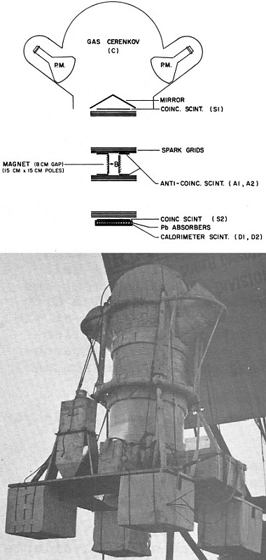
At left we can see a schematic cross section of the spark chamber magnetic spectrometer and a picture of the balloon gondola housing it (click to enlarge). Sixteen spark chamber gaps defined the trajectory of a charged particle before and after its passage through the gap of a permanent magnet. The direction and magnitude of the magnetic deflection determined the charge sign and rigidity of the particle.
Each of the 16 spark chamber modules (also known as "decks") consisted of two parallel 25 x 25 cm2 grids of 0.01 cm beryllium-copper wires with a horizontal spacing of 0.127 cm. The wires of one grid were orthogonal to those of the other grid on the same module, so that both coordinates could be read out. Each wire threaded a ferrite memory core whose state was changed whenever spark current flowed in the wire, storing the information for later interrogation. The spark modules were separated into two "chambers" of eight decks each, one above and one below the magnet. Each chamber was divided into two tiers of four decks each. The spark chamber gas used was a 90% neon / 10% helium mixture, with 0.5 percent ethanol and 1 percent argon added, at a total operating pressure of 1 atm.
The master coincidence signal (triggering C-S1 and S2 but not A1 and A2) was generated by a five-element particle telescope consisting of a gas Cerenkov counter C; two plastic scintillator counters SI and S2, set to trigger on signals above about half that from a singly charged minimum ionizing particle; and two anticoincidence counters A1 and A2. This master coincidence caused the spark chamber to be triggered and read out (and gates the pulse-height analyzers for the shower counters). The Cerenkov counter was filled with 1 atm of C02. For a downward-moving particle, the light was reflected by plane mirrors into two 22 cm photomultipliers outside the telescope field of view. The inside of the dome was painted black to absorb light produced by upward-moving particles. The counters S1 and S2 were 25 x 25 cm2 sheets of 0.475 cm plastic scintillator, each viewed by a single 5 cm photomultiplier tube. The anticoincidence counters, above and below the magnet, were plastic scintillators with 15 cm x 8 cm holes (the same dimensions as the magnet gap), each coupled by two adiabatic light pipes to two photomultiplier tubes located outside the spark gas enclosure.
The geometry of the telescope was determined by (S1-S2) with the Cerenkov counter providing only a velocity threshold and rejection of upward-moving particles. The instrument had a geometrical factor of 19 cm2 sr for rigidities above 50 MV. For lower rigidities the geometry factor was limited by deflection in the magnet which became zero at about 15 MV. The permanent magnet had pole faces 15x15 cm2 and a gap of 8 cm. Its central field was about 1 kilogauss, and it had a vertical line integral of about 25 kilogauss/cm.
In principle, the Cerenkov counter should reject all nucleonic cosmic rays in the rigidity range of interest. However, the low light intensity produced by electrons traversing the Cerenkov gas required this discriminator to have a very low threshold. As this could lead to undesired triggers due to dark noise in the two large photomultipliers a shallow calorimeter was placed below the S2 counter. This subsystem contained two plastic scintillators (D1 and D2) at depths of 1 and 3 radiation lengths (rl) in a 4 rl stack of lead plates. Each of these scintillators was viewed, via an adiabatic light pipe, by a 7.5 cm photomultiplier whose output was digitized by a pulse-height analyzer when a master coincidence occured.
Data generated by the experiment were encoded and telemetered to the ground in a PCM (pulse code modulation). Three-quarters of the bit rate was available for spark chamber data, the rest being devoted to housekeeping data and telemetry synchronization.
The experiment was mounted in a flat plywood panel that served to house the balloon control instrumentation, batteries for operation and ballast hopper. Strong tubing structure around the chamber and crush pads below the platform served to protect the instrument at landing.
Details of the balloon flight
Balloon launched on: 7/3/1972 at 3:59 utc
Launch site: Fort Churchill Airport, Manitoba, Canada
Balloon launched by: Raven Industries Inc.
Balloon manufacturer/size/composition: Zero Pressure Balloon Winzen Stratofilm 18.500.000 cuft - Natural Shape (0.6 mils) - 2 Caps (0.6 Mils.)
Balloon serial number: SF 363.49-060-NSC-03 SN: 10
Flight identification number: Raven Nº 1321
End of flight (L for landing time, W for last contact, otherwise termination time): 7/3/1972 at 5:11 utc (L)
Balloon flight duration (F: time at float only, otherwise total flight time in d:days / h:hours or m:minutes - ): 1 h 11 m
Landing site: Premature Termination. Payload landed 40 miles S of Ft. Churchill, Manitoba, Canada
Campaign: SKYHOOK 72
Payload weight: 1462 lbs
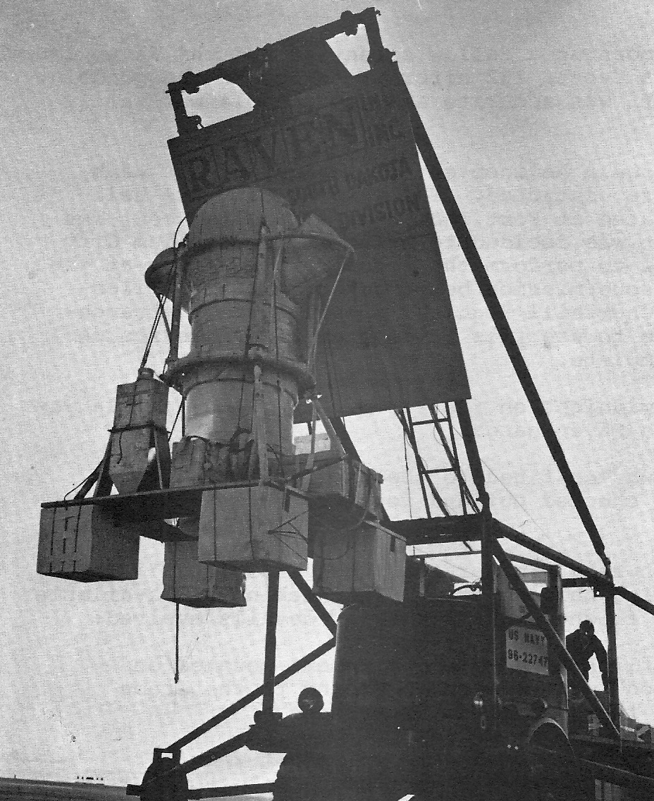
The balloon was launched by dynamic method at 4:00 utc on July 3, 1972 from the airstrip in Fort Churchill airport. Launch was performed smoothly after the launch truck maneuvered some 200 feet to position the gondola for lift off. A normal ascent began at 750 to 800 FPM. Tropopause height was 36,000 feet, at which point the balloon began to cool and slow its ascent. The control center transmitted a ballast command. Seconds later telemetry indicated the system was descending on the parachute. The descending experiment was tracked to impact 45 miles south of Fort Churchill.
The following morning a Cessna 182 located the gondola in the presumed landing spot. Recovery required a helicopter so it was decided to bring in the Uranium City helicopter crew to perform the recovery. Shortly after midnight on the 4th of Julyr the gondola was returned to the launch base. Impact damage was confined to the expendable crush pad. The instrument was checked out and found to be in very good condition.
External references
- Measurement of cosmic ray positron and negatron spectra between 50 and 800 MeV. Ph.D. Thesis by J. K. Daugherty, University of Maryland
3575If you consider this website interesting or useful, you can help me to keep it up and running with a small donation to cover the operational costs. Just the equivalent of the price of a cup of coffee helps a lot.


