Purpose of the flight and payload description
The MISO gamma ray telescope was a cooperative development by research groups from Laboratorio di Fisica Cosmica e Tecnologie Relative del C.N.R., Milano, Italy and the Department of Physics, University of Southampton from England, hence the instruments name. The instrument was built specially for observing the low energy gamma spectrum (0.2-20 MeV) from a balloon in the stratosphere.
THE GAMMA-RAY TELESCOPE
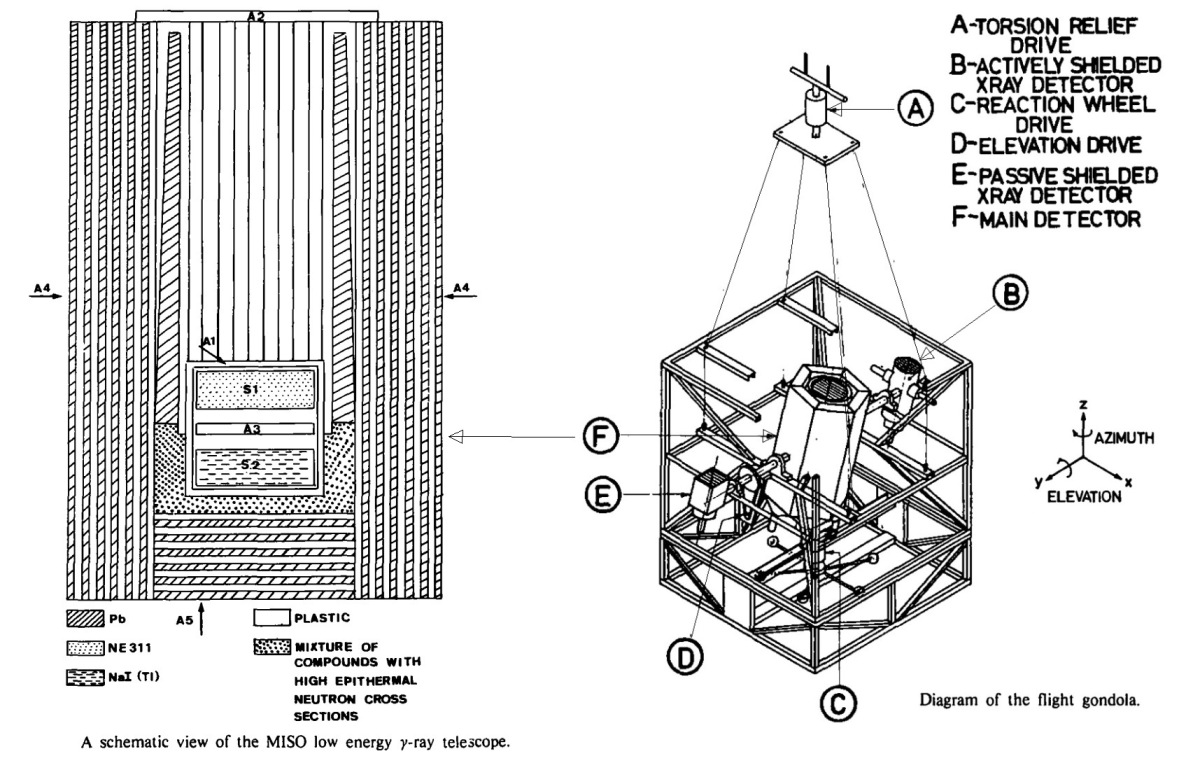
A schematic diagram of the detector can be seen clicking in the figure at left which shows an schematic drawing of the gondola. The central detector consisted of two scintillation counters S1 and S2 which were completely surrounded by a plastic anticoincidence counter (A1), and separated by an independent anticoincidence counter (A3). The detector S1 was a liquid scintillator (NE311) and S2 was a large NaI(T1) crystal. The diameter of each counter was ~27 cm, the depth 10 cm and the separation between them 3 cm. The detector S1 provided the target material in which the incoming photon underwent a Compton collision. The scattered photon then interacted again in S2. The anticoincidence jacket A1 provided a veto for charged particle events which deposited energy in S1 and S2. The signal from the A3 counter eliminated those events in which a charged particle passed from S1 to S2. The central detector system was shielded from atmospheric gamma-rays by lead/plastic scintillator sandwiches A4 and A5, which incorporated six radiation lengths of lead interspersed between six thin plastic scintillators.
The background effects caused by charged particles passing through the aperture of the telescope were effectively eliminated by a thin plastic scintillator (A2). The cylindrical lead collimator situated inside the semiactive shield provided an aperture of about 10° fwhm for gamma-rays in the energy range of interest. The lower half of the central detector was surrounded by a jacket designed to act as a neutron shield. This containED a mixture of boron, tungsten, and lithium, chosen for their high neutron absorption cross-sections, set in a wax moderator. The shielding efficiency extendED over thermal and epithermal neutron energies.
To enable the spectral range of the observations to be extended to lower energies, two independent high energy X-ray detectors were mounted on the same axis as the gamma-ray telescope. One of these was the prototype of a new actively-shielded detector. Data from these detectors covered the energy range from about 20 keV to 250 keV and provided a valuable overlap with other observations. The data were processed by an on-board electronic system which selected the events. The scientific, orientation and housekeeping data were encoded for PCM transmission at 40 kbits/s. Gamma and X-ray events were timed with precision accuracy of 0.75 ms.
THE GONDOLA
The gondola was constructed in two parts. The gamma-ray detector together with the two X-ray detectors were mounted on an elevation axis in the upper section. The lower module was the azimuth orientation platform. This module also provided the batteries, balloon flight electronics and ballast hopper attachments. A four point suspension was used to connect the gondola to a torsion relief motor and hence to the main support from the balloon system.
A three axis magnetometer was used to sense the direction of the earth's magnetic field vector and, when used in conjunction with a resolver-synchro system, produced an azimuth error signal. The direction of the payload with respect to the earth's magnetic field could be be changed by updating the position of the resolver-synchro shaft by telecommand.
Rotation of the payload beneath the balloon was achieved using a reaction wheel to provide a good dynamic response and a torsion relief drive above the payload to prevent the suspension cables twisting. The torsion relief drive also provided a steady torque for continuous rotation in azimuth when required. The tacho-generator was attached to the reaction wheel drive to provide a signal proportional to the angular velocity of the payload.
This rate signal was combined with the position error signal to give the desired servo response. A sun tracker was used to give accurate measurements of the solar azimuth with respect to the payload in order to improve the absolute azimuth pointing accuracy. The elevation axis was referenced to the local vertical and was set by telecommanding the elevation drive to the required position.
Details of the balloon flight
Balloon launched on: 10/7/1978 at
Launch site: Columbia Scientific Balloon Facility, Palestine, Texas, US
Balloon launched by: National Scientific Balloon Facility (NSBF)
Balloon manufacturer/size/composition: Zero Pressure Balloon Winzen - 1.121.350 m3 (20.32 Microns Stratofilm)
Flight identification number: 1096P
End of flight (L for landing time, W for last contact, otherwise termination time): 10/7/1978
Balloon flight duration (F: time at float only, otherwise total flight time in d:days / h:hours or m:minutes - ): F 6 h 50 m
Payload weight: 2858 kgs
Although a full programme of observations had been planned for the flight, the balloon veered in the direction of the Gulf of Mexico after only a few hours at float altitude and only very limited observations were possible.
External references
- A low energy gamma ray observation of the region containing CG 195+4 Astronomy and Astrophysics, vol. 117, no. 1, Jan. 1983, p. 38
- A Search for Low Energy gamma-ray Emission from the Region of the Sky Close to CG135+1 16th International Cosmic Ray Conference, Vol. 12, Pag. 32 (1979)
- Low energy gamma-ray observations of CG135+1 and CG195+4 Advances in Space Research, vol. 1, no. 13, 1981, p. 231
- Low-energy gamma-ray emission close to CG 135 + 1 Astrophysical Journal, Part 2 - Letters to the Editor, vol. 239
- Low-energy gamma-ray sources observed by the MISO telescope Nuovo Cimento C, Serie 1, vol. 7 C, Nov.-Dec. 1984, p. 805
- National Scientific Balloon Facility Annual Report FY 1979 National Center for Atmospheric Research, September 1980
- The MISO low energy gamma -ray telescope Nuclear Instruments and Methods, Vol. 158, p. 595, 1979
If you consider this website interesting or useful, you can help me to keep it up and running with a small donation to cover the operational costs. Just the equivalent of the price of a cup of coffee helps a lot.
