Purpose of the flight and payload description
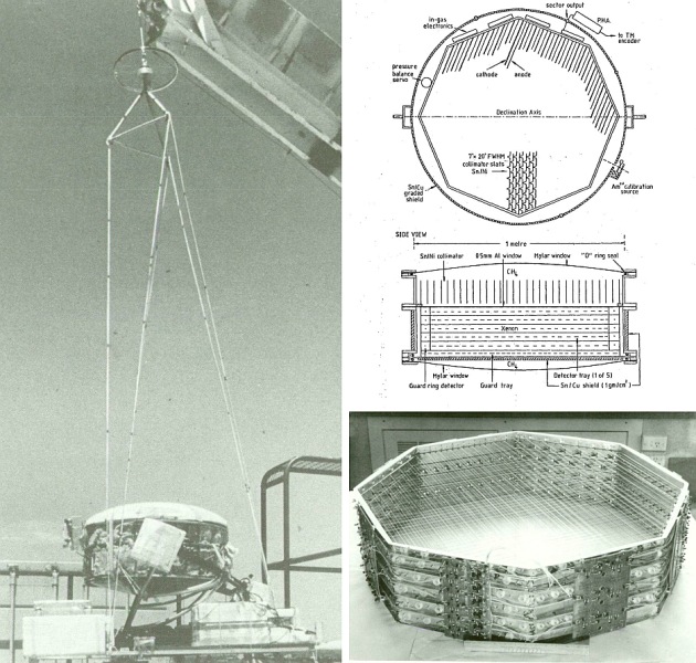
The X-ray detector was a multi-layer proportional counter of 5200 cm2 effective area filled with a xenon-helium-methane gas mixture to slightly above atmospheric pressure. It was sensitive to photons in the energy range 10-100 keV and was specifically built for balloon-borne X-ray astronomy. At left we can see an scheme of its conformation (click to enlarge).
It comprised six octogonal trays stacked one above the other to give an octogonal cylinder with a sensitive region 95 cm along a diagonal and 21 cm deep. The detector was of wall-less construction in which the sensitive region was surrounded on all sides except the entrance window by cathode wires rather than solid walls. Charged particles entering the detector were sensed by the veto counters, amplified and employed in analogue switching circuitry, thus rejecting the subsequent counter pulses. Shielding from atmospheric X-rays was provided by a graded shield of Sn (in the form of pewter) and Cu. The active volume of the counter consisted of five octagonal stacked trays, each with twenty one anodes. These anodes were connected together in groups of three called 'cells'. The thirty five cells each had their own preamplifiers attached to the counter support frame within the gas detection volume. The preamplifier outputs were fed through five convenient locations around the cylinder circumference where they were added together via gain matching resistors.
Collimation of the X-rays was achieved by a slat collimator having a field of view of 7º x 20º FWHM constructed from nickel-plated pewter sheet modules stacked alongside one another above the xenon filled volume and separated from it by a 0.5 mm aluminium window. The collimator section of the telescope was filled with CH4 or CO2 and was also connected to a small end section below the counter.
The multiwire proportional counter was housed in an hermetically sealed pressure vessel of 1 metre diameter, fabricated from aluminium and mylar. This vessel was divided into two sections, the lower half containing the counter whilst the upper section housed the collimator. The whole counter and collimator vessel was equatorially mounted on a frame constructed from one inch aluminium tubing, that also supported the batteries, telemetry encoder electronics, receiver and transmitter and the azimuth servo-stabilization circuitry. Azimuthal stability was achieved by sensing the local geomagnetic field with two orthogonal, horizontally mounted fluxgate magnetometers and applying the resulting magnetometer error signal (derived from the offset of the payload azimuth from true north) to a reaction wheel system which was located at the top of the payload suspension rigging. The support frame was designed so that it would absorb the impact of landing, through deformation and thus protect the X-ray counter from damage.
With the payload stabilized in azimuth the telescope could be pointed at particular source positions by ground commands.
Details of the balloon flight
Balloon launched on: 11/30/1977
Launch site: Australian Balloon Launching Station, Alice Springs, Australia
Balloon launched by: ABLS Mildura
Balloon manufacturer/size/composition: Zero Pressure Balloon
Flight identification number: HIBAL-687
End of flight (L for landing time, W for last contact, otherwise termination time): 11/30/1977
Landing site: Balloon failure at launch. Aborted fligth
Flight preparations of the payload were started in early November 1977 at the Australian Balloon Launch Station site at Alice Springs airport, Central Australia. The flight was attempted on 30th November but was aborted when the balloon failed to lift the payload, draggin it across the airfield. The launch failure appeared to be due to a leak from the balloon. High ground winds over the next weeks prevented any further opportunity for a launch in 1977.
External references
- Galactic X-ray sources and their radio counterparts Duldig Marc, PhD thesis, University of Tasmania, 1981
14118If you consider this website interesting or useful, you can help me to keep it up and running with a small donation to cover the operational costs. Just the equivalent of the price of a cup of coffee helps a lot.


