Purpose of the flight and payload description
The general purpose of the STARGAZER program was to test the feasibility of doing astronomical research from a manned balloon-borne vehicle.
It was initiated in 1957 at the Smithsonian Astrophysical Observatory by the Air Force Office of Scientific Research. Later, the program was under the sponsorship of the Air Force Cambridge Research Laboratories and the scientific portion was conducted at Dearborn Observatory, Northwestern University under the guidance of Dr. Allen Hynek. In association with Dearborn Observatory, the Experimental Astronomy Laboratory of the Massachusetts Institute of Technology was responsible for the telescope mounting and stabilization system and the Naval Ordnance Test Station furnished a scientific assistant and technical assistance in the design and construction of the instruments. Finally, Wright-Patterson Air Force Base was responsible for the gondola and its fittings and the high altitude indoctrination of the observer and the R&D test branch of AFCRL was responsible for the balloon launch operation.
The project included several unmmaned test flights starting in 1960 that would culminate on the only crewed flight in December 1962. Two failed attempts of a second flight were carried out in 1963 just before the project's cancellation.
THE CAPSULE
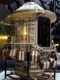
The sealed gondola was an aluminum cylinder 13 feet high and 7 feet in diameter as we can see in the image at left above (click to enlarge). It was originally designed as a platform for a high-altitude escape program, for which purpose it was never used so modifications for STARGAZER were started in 1958.
During flight, the gondola was pressurized to a equivalent one of a height of 22,000 feet. The occupants weared partial pressure suits and partial pressure helmets with the face plates open. The pilot had to operate the communications devices, the equipment necessary to control the balloon's flight, and other instrumentation. He also monitored and controled the environmental control and life support systems of the gondola, e,g. oxygen nitrogen, carbon dioxide, water vapor pressure, and the interior temperature. An ordinary aircraft altimeter gived readings in the normal range of aircraft to 50,000 feet. Above this, a special aneroid barometer indicated the altitude. Two way communication was maintained with the ground at all times. UHF radio was used for linking the balloon crew with the ground, with an alternate HF channel.
Thermal control of the gondola was accomplished with a passive system wich combined exterior surface coatings and interior materials selected and adjusted for a workable balance in solar absorptivity and radiative infra-red heat emissivity. A dead air space was provided between two layers of aluminium foil outside the gondola for its insultaing effect at lower altitudes.
Inside the gondola itself, aluminized fabric curtains were draped over the walls and also covered the overhead dome of the gondola. They purpose was to be a barrier against constant heat loss specially after the sunset.
The design of the gondola door allowed, in an emergency, both pilot and observer to parachute from the gondola at an altitude of about 20,000 feet.
THE LIFE SUPPORT SYSTEMS
The Oxygen-Nitrogen system furnished breathing oxygen for the crew, pressurization for the partial pressure suits (as required) and pressurization for the sealed gondola. Below the gondola floor were located a 10 liter liquid nitrogen converter and two 10 liter liquid oxygen converters. The liquid nitrogen was forced through an evaporating coil by the build up pressure in the nitrogen converter, and the gas was then passed through a warming coil wich encircled the interior walls of the gondola. After warming up the gas to the gondola temperature, the nitrogen was metered by the pilot through a flowrater by means of a manual needle valve, and dumped directly into the sealed gondola.
The control of CO2 and H2O vapor in the gondola was accomplished passively by chemicals without the expenditure of any power. CO2 was absorbed by Baralyme packed in multilayered screen trays located beneath the crew seats. Circulation of the ambient air over and through the layers of the screen trays was achieved by natural convection.
Both, the pilot and the scientific officer used a partial pressure suit model CSU4P with an integral ventilation suit and a modified HGU8P partial pressure helmet.
In the normal mode, the suits were not pressurized and the face plates were open. Oxygen and nitrogen were metered manually through the flowmeters in a 50-50 mixture, maintaining a cabin internal pressure of 6 psia. If there was a cabin leak, the needle valves regulating the dual gas flow would be adjusted to compensate it, the face plates close automatically and the suits begin supplying oxygen to the wearers. At that time the barometric shuttle valve automatically diverts the oxygen flow downstream from the manual needle valve to the suit and helmet regulator valves.
To monitoring the crew health two physiological parameters were closelly followed during the flight: a electrocardiograph picked up by biaxilliary electrodes, and the respiration rate picked up by a liquid copper sulfate respiration resistance transducer strapped across the chest of the aeronauts. These signals were telemetered to the chase plane by pulse position modulation.
THE TELESCOPE
The key piece of scientific equipment consisted of a Cassegrain reflector telescope with a primary mirror of 12 inches in diameter and a effective focal length of approximately 120 inches. The Ferson Optical Company designed and built the secondary mirror support system wich by a combination of Invar and aluminum components held the focal point to within f 0.001 inch over a temperature range of -60°C to +70 ºC.
The telescope was the first balloon-borne instrument mounted in a platform with gyroscopic-electronic stabilizing gear. The system, developed and built by Massachusetts Institute of Technology's Instrumentation Laboratory, served two purposes. It stabilized the telescope, holding it steady with respect to the stars despite the swaying and spinning of the gondola, and provided an automatic means of maneuvering the telescope -mounted outside- so that it remained pointing at the stars they want to observe. The M.I.T, system included two single-degree-of-freedom gyroscope, and two single-axis star trackers mounted on the cylindrical frame which housed the STARGAZER telescope. One gyro and one star tracker were mounted to sense traverse, or slide to side, motion of the telescope and the remaining gyro and star tracker sensed telescope motion in elevation, up and down. This system hold the telescopy steady despite erratic movement of the gondola as it spined and swayed beneath the balloon. As it was an automatic system, the only way to aim the telescope to a desired point was "to fool it" feeding electrical signals into it. Then, the system reacted as this signals were been caused by disturbing motion of the gondola, and responded accordingly, turning the telescope in train and elevation as desired. This was controled by the crew through a control panel.
THE BALLOON
The balloon manufacturer was J.T Schjeldahl company from Minnesota and was made of reinforced mylar. It had 280 feet high, 200 feet diameter and 3.200.000 cuft of volume.
In the balloon apex was located an electromechanical valve wich allowed the pilot to control the gas release. Also a servo controlled ballast hopper was available, carrying fine steel dust wich can be released as required to reduce the balloon system weight.
Between the balloon and the gondola was a 100 foot diameter recovery parachute which was flown in an extended position throughout flight to facilitate nearly instantaneous opening in the event of a balloon failure or a pilot decision to descend in this manner.
The gondola was hanging below the balloon on a cable giving a total height at takeoff of approximately 400 feet.
Details of the balloon flight
Balloon launched on: 3/26/1963
Launch site: Holloman Air Force Base, Alamogordo, New Mexico, US
Balloon launched by: Air Force Cambridge Research Laboratories (AFCRL)
Balloon manufacturer/size/composition: Zero Pressure Balloon Schjeldahl GT-12 - 3.200.000 cuft (Dacron scrim & Mylar laminate 0.75 mil)
End of flight (L for landing time, W for last contact, otherwise termination time): 3/26/1963
Landing site: Aborted flight.
Payload weight: 4800 pounds
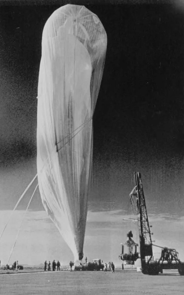
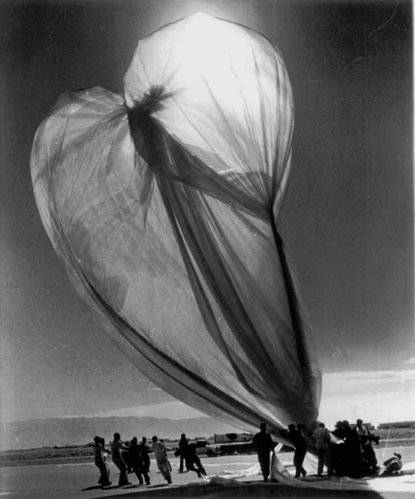
The second mission of the STARGAZER program was meant to be launched at dawn of March 26, 1963. However during prelaunch preparations at Holloman AFB the security system that connects the capsule and the balloon was triggered by an electrostatic discharge and the balloon se parated. When free and due to the wind it became entangled in the tower of the forklift that hoisted the capsule. Balloon crew proceeded to recover the balloon but attempts to patch it on the field by representatives of the company that manufactured it (G.T. Schjeldhal) present at the launch were fruitless and the mission was cancelled. A new attemprt would be made the next month to no avail.
If you consider this website interesting or useful, you can help me to keep it up and running with a small donation to cover the operational costs. Just the equivalent of the price of a cup of coffee helps a lot.


